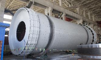
مصنع لتجهيز البوكسيت/Typical Rod Mill Circuit
EField Mill: You may already know that i'm addicted to any kind of sensor measurement appliions. I always wanted to track down the fluctuations of earths magnetic field and i also was fascinated by measuring the ambient electric field of the earth that is mai.
· Circuit Operation. As can be seen in the given circuit diagram, the design is as simple as it can be, just a couple of general purpose transistors and a few other passive components for configuring what looks like a nice little AM radio receiver unit.
Orway Mineral ConsultantsLinkedIn. Learn about working at Orway Mineral Consultants. Join LinkedIn today for free. See who you know at Orway Mineral Consultants, leverage your professional network, These include AG mills, SAG mills, rod mills, ball mills, fine grinding mills, processing, iron ore, hydrometallurgy, process design and commissioning.
Figure 1 shows a typical connection of two hifi components, and includes the house wiring and main earthing point. As can be seen, there is a loop (indied by the dotted line), which includes the interconnect cable, power leads, and a small part of the house wiring.
Double Pump Hydraulic system ( HiLo circuit ) Figure shows a circuit that uses two pumps, one highpressure, lowflow pump and the other lowpressure, highflow pump One can find appliion in a punch press in which the hydraulic ram must extend rapidly over a large distance with very low pressure but high flow requirements.
Introduction to Selecting Milling Tools IImportant decisions for the selection of cutting tools for standard milling operations The variety of shapes and materials machined on modern milling machines makes it imperative for machine operators to understand the decisionmaking process for selecting suitable cutting tools for each job.
BJT Biasing Circuits The DC Operation Point [5] DC Bias: Bias establishes the dc operating point for proper linear operation of an amplifier. If an amplifier is not biased with correct dc voltages on the input and output, it can go into saturation or cutoff when an input signal is applied.
The counterpoise shall be connected to driven ground rods at the lighting vault, where the feeders connect to the lighting circuit, and at intervals not more than 2000 feet apart along the circuit. The ground rod resistance shall be less than 25 ohms. The ground rods shall be not less than 3 feet and preferably 10 from any equipment grounds.
Typical, Basic Milling Machine . Tramming the Head •The head of a vertical milling machine can be tilted from side to side and from front to back. This allows for versatility of the machine, but these adjustments can drift. Occasionally, one should check and adjust the head so that the
comminution circuits used in the gold industry, such as: Multistage crushing and pebble and/or ball milling circuits, typical of older installations. The process design of gold leaching and carboninpulp circuits by W. Stange* * Hatch Africa (Pty) Ltd,, Woodlands Office .
circuit breakers) are allowed to function, removing the source of the fault currents. The National Electrical Code Requirements part of this paper describes equipment grounding procedures used in the United States. System Grounding In system grounding, one of .
· Strain Gauge Resistance. Typical strain gauge resistances range from 30 Ω to 3 kΩ (unstressed). This resistance may change only a fraction of a percent for the full force range of the gauge, given the limitations imposed by the elastic limits of the gauge material and of the test specimen. Forces great enough to induce greater resistance ...
Figure 5 Active Baffle Step Correction Circuit. The circuit above isn't 'active' in the normal sense, as it simply includes an input and output buffer. Although I've shown a TL072 opamp, many people are likely to want something 'better', although it's highly unlikely that there will be any audible difference.
· If the mill rolls 800,000 tons per year, it runs at an average production rate of tons/hour. If the utilization can be improved by 1 %, the available rolling hours is .
OPTOELECTRONICS CIRCUIT COLLECTION By Neil Albaugh AVALANCHE PHOTODIODE BIAS SUPPLY 1 Provides an output voltage of 0V to +80V for reverse biasing an avalanche photodiode to control its gain. This circuit can also be reconfigured to supply a 0V to –80V output. LINEAR TEC DRIVER–1 This is a bridgetied load (BTL) linear amplifier for driving