مصنع لتجهيز البوكسيت/Process Flow Diagram Crushing Plant
The simplest form of process flow diagram is linear. The key steps in the process are identified, laid out step by step, and subsequently verified by the HACCP team. The diagram shows a simple 8step process, where one step follows the next in order: Step 1: Purchase. Step 2: Receipt/Storage. Step 3: Preparation. Step 4: Mixing. Step 5: Cooking.
· Business Processes Flow Charts Process Flow Diagram Flow Chart Template Flow Chart . ... Venn Diagram Animal And Plant Cell . Labelled Diagram Of Plasmolysed Cell . Customer Service Flowchart . 3 Venn Diagram Template . Top Category Plant Cell . Wiring Diagram .
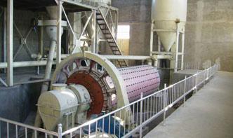
A simplified process flow diagram PDF (58 KB) is attached. ( Download Acrobat Reader ). The gold plant comprises facilities for crushing, grinding, flotation, pressure oxidation (POX), counter current decantation (CCD) washing, neutralisation, carboninleach (CIL) cyanidation and tailings disposal.
Plant Design CHEN 451 Engineering design of new chemical and petrochemical plants and the expansion or revision of existing ones require the use of engineering principles and theories combined with a practical ... A PFD is a simplified flow diagram of a single process unit, a utility unit, a complete process module.
· Process Flow Diagrams. To show a practical process example, let's examine three diagrams for a compressor control system, beginning with a Process Flow Diagram, or PFD. In this fictitious process, water is being evaporated from a process solution under partial vacuum (provided by the compressor).
Flow Diagram Of Crusher. Flow Chart Of Crusher Plant 100 Tph. Flow chart for tph crusher plant Flowchart crushing plant cap 600 tph Flow chart of crusher plant 120 tph flow chart of crusher plant 100 tph plant is designed for 58 5 tph water this will require construction of a new crusher house and a process flow chart in get more free chart of crusher. read more.
Process Flow Diagram is the . foundation The process must be defined step by step, including interfaces The PFD provides the structure to document what product characteristics and requirements (OUTPUTS) are affected by a given operation and how these characteristics and sources of variation are controlled (INPUTS)
· Business Processes Flow Charts Process Flow Diagram Flow Chart Template Flow Chart . ... Venn Diagram Animal And Plant Cell . Labelled Diagram Of Plasmolysed Cell . Customer Service Flowchart . 3 Venn Diagram Template . Top Category .
· Process Flow Diagram (PFD) is a drawing which essentially captures the process flow for a processing plant. PFD is used to capture the main process equipment's, main process stream, process/design conditions in these equipments and the basic process control scheme in .
Process Flow Diagram Caustic Plant Power Plant Pulp Mill Black Liquor Green Liquor White Liquor. The Kraft Pulping and Recovery Basic Process Flow Pulp Mill Dale Proctor, 2003
Process flow maker features. Process flow diagrams illustrate how a large complex process is broken down into smaller functions and how these fit together. As visual tools, they can help your team or organization see the bigger picture as well as where they fit into its entirety.
Natural gas processing plants use physical and chemical processes to separate and recover valuable hydrocarbon fluids from a gas stream. In the processing plant, all the pipes, containment vessels, steam lines, tanks, pumps, compressors, towers, and instruments contain a gas or liquid undergoing some kind of treatment process.
A process flow diagram (PFD) is a diagram commonly used in chemical and process engineering to indie the general flow of plant processes and equipment. The PFD displays the relationship between major equipment of a plant facility and does not show minor details such as piping details and designations. Another commonly used term for a PFD is flowsheet
A Process Flow Diagram (PFD) is a diagram which shows the relationships between the main components in a system. Process Flow Diagrams are widely used by engineers in chemical and process engineering, they allows to indie the general flow of plant process streams and equipment, helps to design the petroleum refineries, petrochemical and chemical plants, natural gas processing plants.
flow process and intermittent flow process. In the line flow process, the product flows from one operation to the next in a prescribed sequence as in the preparation of homogenized and pasteurised milk in an automatic dairy plant. The individual work tasks are closely coupled. There may be side flows, which impinge on this line, but they are ...
Sample1 Manufacturing process flow. Assembly Test 1. Incoming material QC (Visual Inspection) (Quality conformance inspection) 2. Assembly 1 (Injection molding process) 3. Test1 (Visual Inspection) (Electric resistance measurement ) Assembly4. 2 (Welding process) (Coating) Cleaning / Packaging / Labeling Test 6. Test 2 ...
Line Crushing Process Flow Chart lebenstraumin . Manufacturing Process Flow Chart Of Crushing Line process flow chart crushing plant crusherasia flow chart of the production process in a crushing plant process The Zenith is the professional mining equipments manufacturer in the world loed in ChinaIndia along with other Asian marketplaces to develop and develop now we.
diagrams to describe the plant they are working with. The three most common diagrams that are used are Block Flow Diagrams (BFD), Process Flow Diagrams (PFD), and Process Instrumentation Diagrams (PID). Block Flow Diagrams are the simplest diagram and focus on the main operation sections of a given process.
· Figure 3. The above figure shows a detailed process flow diagram (PFD) for the cumene production process. Major pieces of equipment are labeled and the general flow can be visualized. The designation P (, P101) indies a pump. VL indies a valve. R indies a reactor. T indies a distillation column. HE indies heat exchanger.
AND PROCESS DATA SHEETS A1 PROCESS FLOW DIAGRAMS USING VISIO 2002 SOFTWARE Figure 112b Process flow diagram (Feed and fuel desulfurization section). Figure 112c Typical process flow diagram for the production of Methyl Tertiary Butyl Ether (MTBE). Figure 114 Piping and instrumentation diagram for Ammonia plant CO 2 removal. Figure 115 ...
· Process flow diagram for a typical treatment plant via subsurface flow constructed wetlands. At 25 ppb as i can run a system at 40 gpm however at 120 ppb as i need to reduce it down to 10 gpm with the same system to increase contact time. The solids attached to the carbon bed hamper further adsorption process.
Process Flow Diagram Process Flow Diagram (PFD) is a drawing which describesthe process flow for a processing plant. PFD is used to capture the main process equipment and main process streams in a single drawing. White Rose The White Rose Carbon Capture and Storage project.
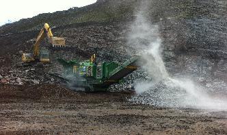
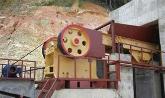
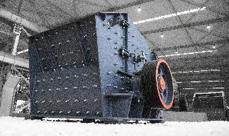
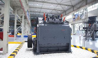
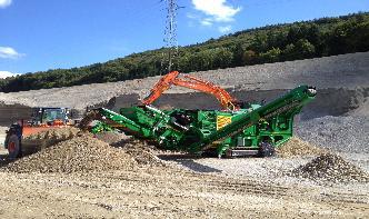
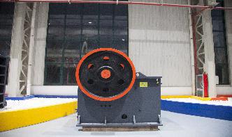
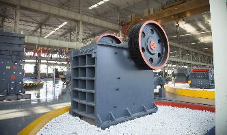
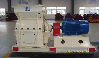
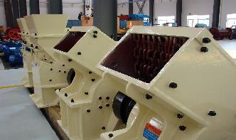
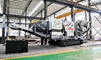
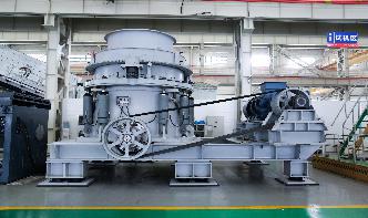
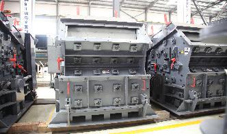
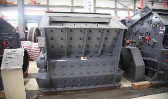
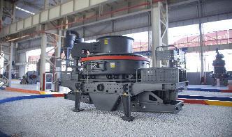
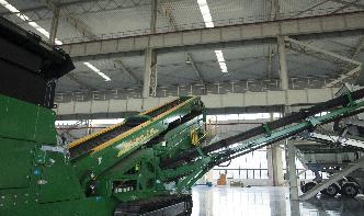
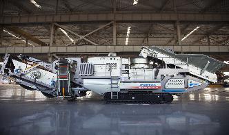
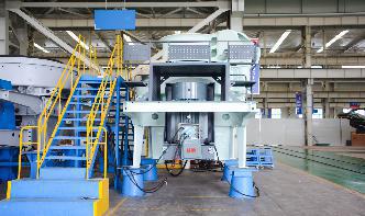
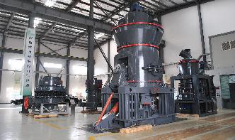
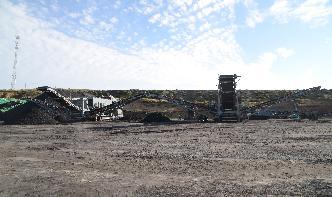
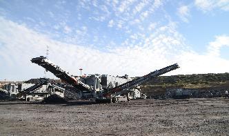
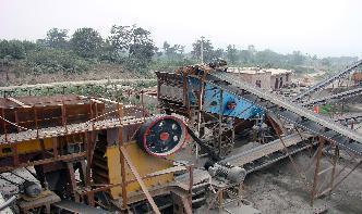
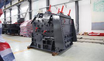
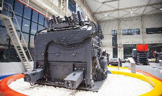
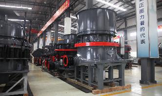
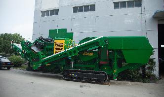
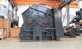
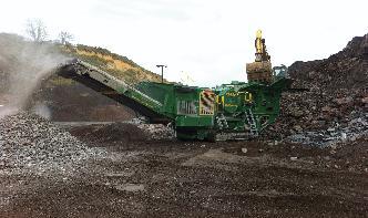
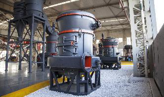
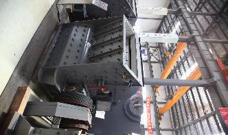
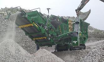
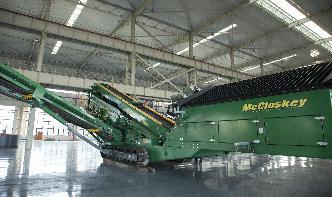
Process of crushing plant. Raw materials are evenly and gradually conveyed into jaw stone crushing equipment for primary crushing via the hopper of vibrating feeder. The crushed stone materials are conveyed to crushing plant by belt conveyor for secondary crushing before they are sent to vibrating screen to be separated.